Demanding environmental, labor and productivity standards in today’s manufacturing industry, with special emphasis on those areas where raw materials in dust phase are transported and processed, require the implementation of suction and filtering systems that guarantee on the one hand the elimination of pollution sources, as well as the improvement in process performance through product recovery.
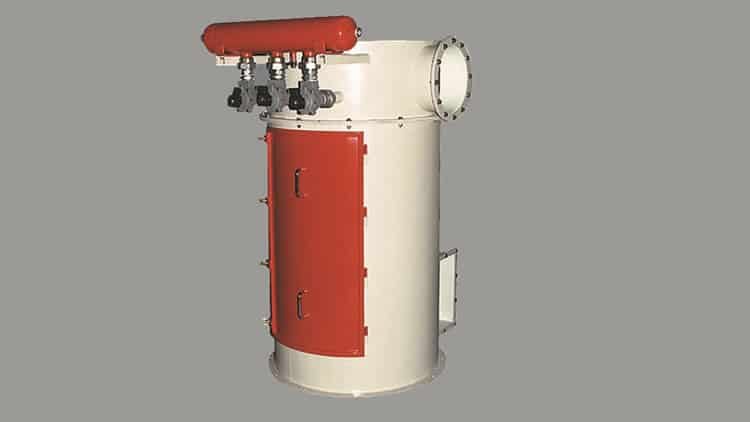
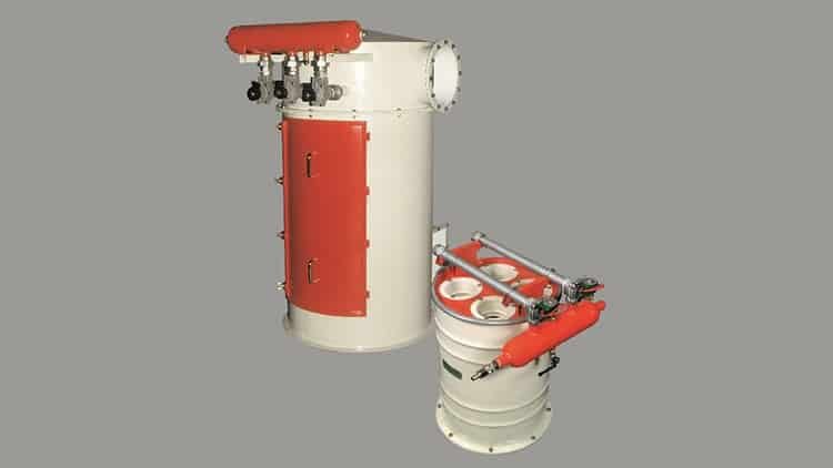
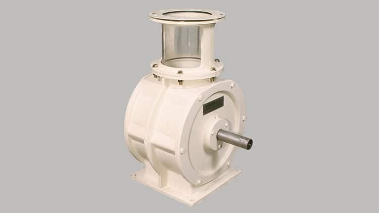
Of the various types of existing suction installations, and focusing on localized dust extraction systems, we can basically distinguish two highly widespread configurations in the industry:
How is the most appropriate suction system determined and sized?
First of all, the general typology best suited to the need must be determined. For this we have basically 2 alternatives:
Once the typology has been determined, the intervening elements must be sized, of which the most important is the filter. Its determination has 2 stages:
1- Centralized industrial dust collectors
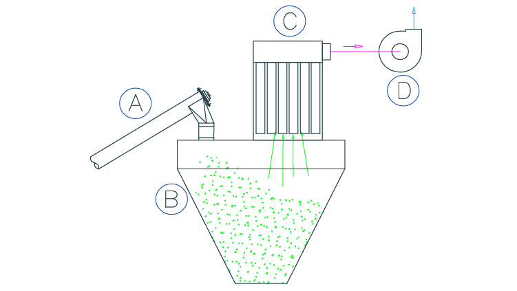
It is a suction system whose purpose is to collect the pollutant as close as possible to the point where it was generated in one or more sources, conveying it to the collecting device.
There are 4 main components:
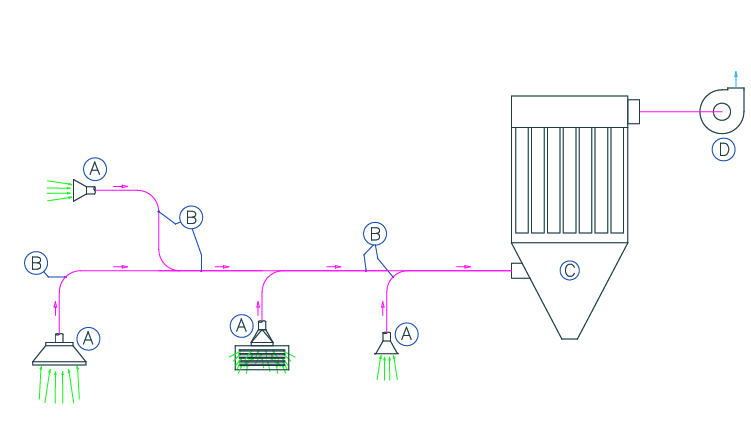
A- Capturing device: Typically bells or hoppers through which contaminants are captured. It must have the appropriate geometry that allows the dust to be dragged.
B- Aspiration ducts or piping: In charge of conducting the air loaded with the contaminant at the appropriate speed.
C- Purifying or separating equipment: It fulfills the function of receiving the dust together with the air and separating it from it. The most common are cyclone separators, bag filters, dust collectors, etc.
D- Impeller or air generator: Generally these are centrifugal fans that provide the energy necessary for the air with dust to circulate through hoods, ducts and separator, ensuring the flow and pressure necessary to overcome the restrictions of the conduction circuit (system pressure drop).
2. Compact or plug-in industrial dust collectors
3. Bag filters - How do they work and what are the types of bag filters?
Within the group of scrubbers or separators used in localized aspiration systems, bag filters are the most widespread and representative equipment for the separation of solids in a gaseous flow. They have inside them filtering elements made of technical textiles.
Fabric filters separate particles by obstruction, impact, interception, diffusion and electrostatic attraction. The fabric is made of fibrous materials, natural or synthetic, and can be woven or non-woven (felts). The advances of the last decades in the production and development of nonwoven textiles (needlepunch fabrics), have made them prevail due to their improved mechanical, chemical and high temperature resistance.
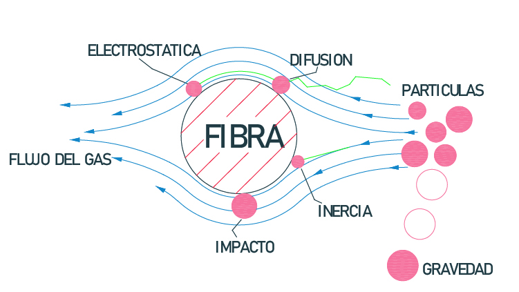
Needlepunched cloths are identified by their thickness and weight per unit area. The fabric or filter media is porous, and therefore allows air to circulate through it, retaining particles on its “dirty” side. Another parameter that identifies the textile is its permeability, which is defined as the volume of air that passes through a surface in a unit of time with a given pressure difference. The combination of both parameters determines the retention efficiency of the filter cloth.
The needlepunched fabrics used in filtration have a mesh that provides mechanical resistance to the textile. On the other hand, manufacturers apply a treatment on the side that will be in contact with the dust (generally flamed), thus presenting a smooth surface that will facilitate the detachment of the material retained on the surface. The maximum retention efficiency is obtained progressively, until the smallest particles that are retained generate the so-called “filter cake”. For this reason, in some cases, the so-called “preloading” is performed, which achieves the necessary filtering capacity by introducing into the circuit inert material of controlled granulometry that generates this cake.
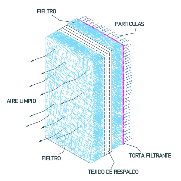
Due to the accumulative impregnation of material, baghouses are equipped with systems that help to remove the retained dust, called cleaning or self-cleaning system.
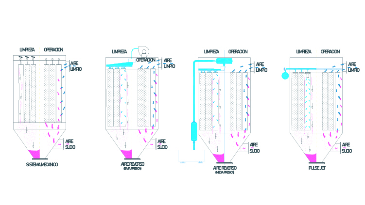
The main self-cleaning systems are:
a- Mechanical: shaking, vibration, etc.
b- Low pressure counter current air injection: With centrifugal fan with pressures in the order of 0.035 – 0.050 bar.
c- Medium pressure counter current air injection: With Roots type blower with pressures of approximately 0.4 – 0.5 bar.
d- Compressed air pulses or pulse jet: With high pressure compressors between 5 to 6 bar.
Components of the self-cleaning system:
Based on the filters with “Pulse Jet” cleaning system, which is the most common, we can describe the following components:
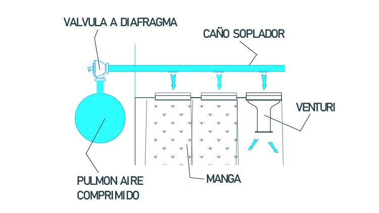
- Compressed air buffer tank.
- Diaphragm valves with pneumatic or electric pilot, in charge of achieving the air pulses or shots for cleaning.
- Pipes or blowing flutes, in charge of introducing the compressed air pulses inside each sleeve.
- Accessories of conduction and connection of the compressed air circuit.
- Accelerator or Venturi tubes (many times they are part of the sleeve holder baskets).
- Programmable electronic sequencer, in charge of managing the sequence and duration of the cleaning cycles. Often associated or including a differential pressure gauge that enables the enabling of the cleaning cycles according to demand, within a range of previously set pressures.
The cleaning cycle does not interrupt suction. The usual configuration involves 200 to 500 millisecond pulses of a jet of compressed air at a pressure of between 5 and 6 bar. The pulse is transmitted to a line of hoses (generally no more than 14 hoses per row) and the usual frequency is in the order of 30 – 120 seconds between blows. These cycles of shots may be uninterrupted, or according to need, if a pressure switch is available to monitor the saturation state of the filtering fabric.
4. Baghouse and fan selection and sizing
Regarding the selection and sizing of equipment, the physical-chemical characteristics of the product, type and characteristics of the emission points, pollutant concentration, conditions of the site and/or environment of the installation, requirements and regulations, etc. must be taken into account.
This information allows the designer of localized aspiration installations to calculate the ideal aspiration flow rate, the necessary filtering surface, characteristics of the filtering elements and other elements of the system.
Among the parameters for the selection or sizing of bag filters, the filtering velocity, also known as “air to cloth ratio” or filtering ratio, stands out. It is defined as the maximum flow rate in m³/min of contaminated air that can pass through 1 m² of filtering surface. It is established according to the characteristics of the product to be filtered, its granulometry and concentration, type of filter, etc.
The filtration ratio for our air pulse self-cleaning filters ranges from 1 to 6 (m/min). Although there are tables and empirical formulas that allow us to approximate the ideal value for each contaminant, in general we resort to an analysis of samples of the material, background and previous experiences.
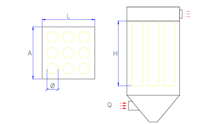
Vf = Q / Aft y
Aft = π · Ø · H · n
Where:
Vf= Velocity or filtration ratio (m/min).
Q = Flow rate of contaminated air (m³/min.)
Aft = Total filtering area (m²)
Ø =Hose diameter (m)
H = Bag length (m)
n = Number of bags
The other important parameter when sizing a baghouse is the can velocity, defined as the upward velocity of air through the open area between the filter bags within a dust collector. If the interstitial velocity of the upward airflow is too high, the dust expelled from the bags during cleaning will not decant into the lower hopper. Instead, it will be reincorporated and carried back to the bag surface, causing pressure drop, excessive use of compressed air and shorter bag life. A typical can velocity value is 0.5 to 1.2 m/sec.
Vi = Q / (At-Am) y
At = A · L
Am = (π · Ø² · n) / 4
Where:
Vi = Interstitial velocity (m/sec).
Q = Air flow rate (m³/sec.)
At = Cross sectional area of the filter (m²)
Am = Cross sectional area of the bags (m²)
A and L = Sides of the filter (m)
Ø = Bag diameter (m)
n = Number of bags
